30+ inverter circuit block diagram
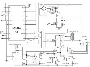
The dead time is controlled by a resistor to ground on RDT pin 9. 500 Watt Inverter Circuit Figure 5.

12v To 220v Inverter Circuit Diagram Pcb Layout Circuit Diagram Electronic Circuit Design Electrical Circuit Diagram
Sine Wave Inverter Control technique Block Diagram The triggering pulses are obtained at the point of intersection of the carrier and a reference signal sine wave.
. This electrical device that transforms the AC power supply frequency the VFD circuit comprises three parts. Qasim Hameed Firas Mohammed Ali Al-Raie -32 - Figure 1 4 shows the schematic diagram of the final inverter circuit. 162 the primary aim of the converter circuits in PV systems is to deliver the maximum power to the load side stand-alone or grid connected.
PV Solar Inverter Circuit diagram. As it is illustrated in block diagram forms in Fig. These parts are a full-wave bridge rectifier DC link and an inverter.
30 Waveform During the Charging Mode. In regulated power supplies a circuit continually samples a portion of the output voltage and. In such a case the simplified circuit can be drawn as below.
So for 120 to 180. Can I Get A Connection Diagram Of Solar Panel And Inverter Quora. A dead time circuit is provided to prevent shoot through currents in the power output stage.
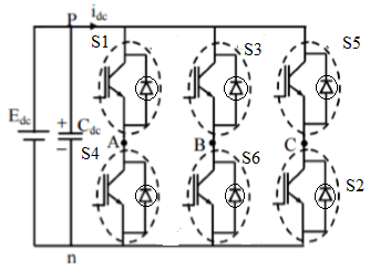
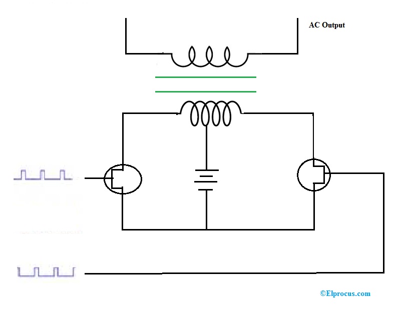
Circuit Diagram Of A Three Phase. Inverter circuit gives Alternating Current AC output from battery Power source but the battery. The High-Side FET is Switched Off and Both Lower-Side FETs to.
Block Diagram Regulated Supply. How An Inverter Works Working Of With Block Diagram Explanation. The dead time selected should.
For 120 to 180 S1 S3S6 are closed while the remaining three switches are open. The 5V DC input voltage of the AT89C51 microcontroller and the 74LS244. 800VA Pure Sine Wave Inverters Reference Design Application Report.
The 3-single phase inverters place across the similar DC source and the pole voltages within a 3-phase inverter are equivalent to the pole voltages within 1-phase half-bridge inverter.
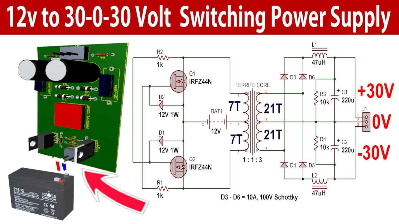
30 0 30 Volt 500w Switching Power Supply For Power Amplifier Youtube Power Supply Circuit Power Amplifiers Circuit Diagram

Gpic Power Converter Control Development System Mini Scale Skiip3 Replica Back To Back Converter Ni Community
![]()
Dc To Ac Inverter Circuit Working Limitations And Applications

How To Design Filter Circuit Of Inverter Quora
Notes On The Troubleshooting And Repair Of Electronic Flash Units And Strobe Lights And Design Guidelines Useful Circuits And Schematics
Which Are The Types Of Transistor Used In An Inverter Quora

Gpic Power Converter Control Development System Mini Scale Skiip3 Replica Back To Back Converter Ni Community
Can I Have A Practical Inverter Circuit Quora
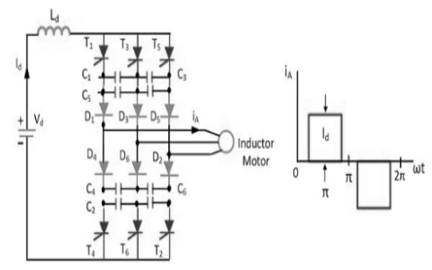
Current Source Inverter Circuit Diagram And Its Advantages

Gpic Power Converter Control Development System Mini Scale Skiip3 Replica Back To Back Converter Ni Community
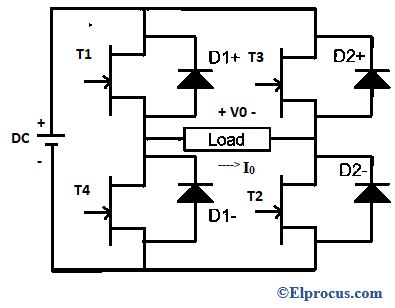
Full Bridge Inverter Construction Working And Applications
Pwm Inverter Definition Circuit Diagram Working And Applications
Three Phase Inverter Circuit Working And Its Applications
2
Inverters Working Different Types Circuit Working And Its Applications
Sam S Laser Faq Complete Hene Laser Power Supply Schematics
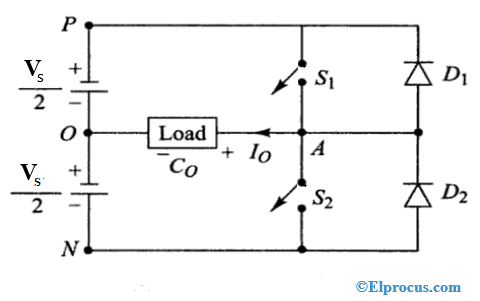
Half Bridge Inverter Circuit Diagram Advantages Its Disadvantages